Introduction
Welcome to the second part of our Lacuna Space guide. In part one of this series, we laid the groundwork by introducing the technology, walking you through the IoT stack, and breaking down the core hardware and software components that make satellite-connected IoT possible.
In this article, we move from theory to practice and zoom in on how data actually travels - from a constrained device in the field, through space, and into cloud platforms you can work with. If you haven’t read part one yet, it’s worth starting there for context before diving into the details below.
Overview of LoRaWAN Protocol for IoT Communication
LoRaWAN (Long Range Wide Area Network) is a key communication protocol in low-power IoT applications, especially for devices that need to transmit data across long distances.
There are two methods for activating a connection in LoRaWAN:
- OTAA (Over-the-Air Activation): OTAA is the preferred method for LoRaWAN devices on terrestrial networks. In this method, the device dynamically joins the network by exchanging keys with a LoRaWAN server. This approach is secure and flexible, but it requires downlink communication from the server, which isn’t always feasible in satellite systems like Lacuna Space.
- ABP (Activation by Personalization): Since downlink communication isn’t available in Lacuna’s satellite network, ABP is used instead. With ABP, devices are manually configured with network keys and parameters, bypassing the need for over-the-air key exchanges. This makes ABP the default choice for Lacuna Space, as it doesn’t rely on continuous connection to a LoRaWAN server.
LoRaWAN defines three device classes—Class A, Class B, and Class C—each optimized for different power consumption and latency requirements:
- Class A: The most energy-efficient, where devices receive downlink messages only after transmitting uplink data, making it ideal for low-power applications.
- Class B: Introduces scheduled “ping slots” for downlinks at regular intervals, allowing for more predictable communication.
- Class C: Enables continuous listening for downlink messages, reducing latency at the cost of higher power consumption.
Registering a Device in TTN for Satellite Communication
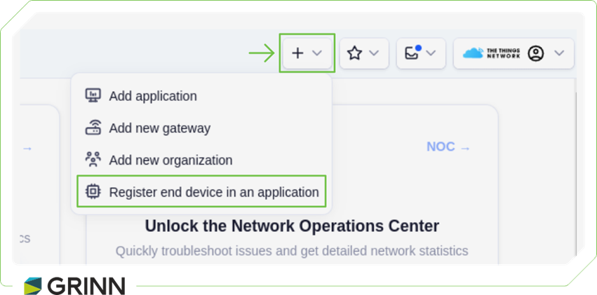
- Open and log in to The Things Network Console.
- In the chosen application, select Register End Device.
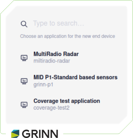
- Next, choose the application where you want to add the device.
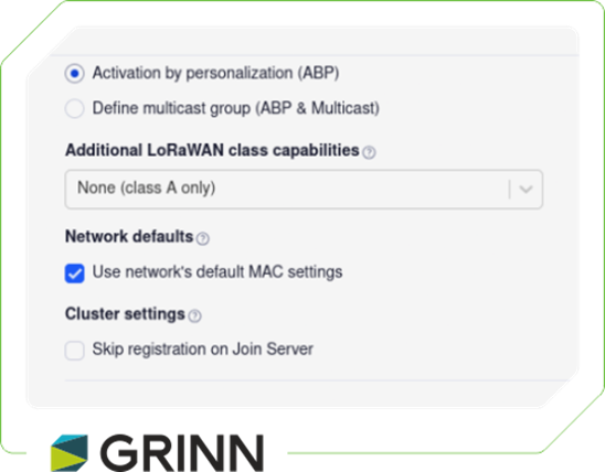
- Choose ABP and the default MAC settings. All fields should generate automatically to prevent repetition. It’s also helpful to assign a clear, meaningful name to the device for easier identification later.
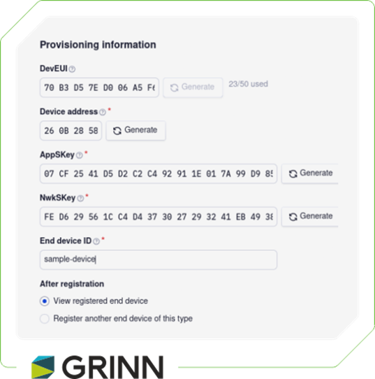
After registering the device in TTN, configure the generated keys and device address on the device. This can be done using the CLI. For example:
satellite set_device_address 260BDABB
satellite set_app_key EBD17CBDA6232C73A2CEF1D1E8FD40D3
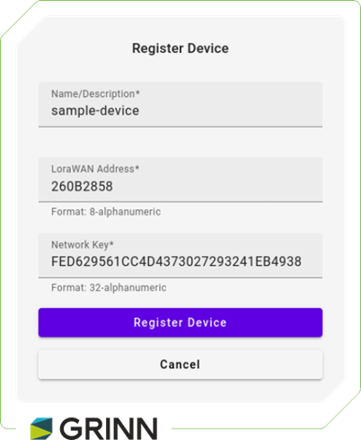
Registering a Device in Lacuna Space Dashboard
Registering the device in the Lacuna Space Dashboard is straightforward. Simply copy the NwkSKey into the Network Key field and the Device Address into the LoRaWAN Address field.
Zephyr Application Setup: Configuring Hardware Peripherals
Since we’re using Zephyr, the first step is to modify the Device Tree Source (DTS) file to define the hardware peripherals—such as SPI, I2C, and UART—required for the application. This step ensures that all necessary devices and pins are correctly configured and recognized by the Zephyr build system.
&i2c1 {
      pinctrl-0 = <&i2c1_scl_pb6 &i2c1_sda_pb7>;
      pinctrl-1 = <&analog_pb6 &analog_pb7>;
      pinctrl-names = "default", "sleep";
      status = "okay";
      clock-frequency = ;
      shtcx: shtcx@70 {
            compatible = "sensirion,shtcx";
            reg = <0x70>;
            chip = "shtc3";
            measure-mode = "low-power";
      };
};
      lr1120: lr1120 {
            lr1120_reset: lr1120_reset {
                  compatible = "grinn,io-output";
                  gpios = <&gpioa 0 GPIO_ACTIVE_LOW>;
            };

            lr1120_433_en: lr1120_433_en {
                  compatible = "grinn,io-output";
                  gpios = <&gpiod 0 GPIO_ACTIVE_HIGH>;
            };
            lr1120_cs: lr1120_cs {
                  compatible = "grinn,io-output";
                  gpios = <&gpioa 4 GPIO_ACTIVE_LOW>;
            };
            lr1120_inputs: lr1120_inputs {
                  compatible = "gpio-keys";

                  lr1120_dio9: lr1120_dio9 {
                        gpios = <&gpiob 3 (GPIO_PULL_DOWN)>;
                  };
                  lr1120_busy: lr1120_busy {
                        gpios = <&gpiob 0 (GPIO_PULL_UP)>;
                  };
            };
      };

      radar: radar {
            radar_en: radar_en {
                  compatible = "grinn,io-output";
                  gpios = <&gpioc 10 GPIO_ACTIVE_HIGH>;
            };
            radar_ctrl: radar_ctrl {
                  compatible = "grinn,io-output";
                  gpios = <&gpioc 11 GPIO_ACTIVE_HIGH>;
            };
            radar_cs: radar_cs {
                  compatible = "grinn,io-output";
                  gpios = <&gpiob 12 GPIO_ACTIVE_HIGH>;
            };
            radar_inputs: radar_inputs {
                  compatible = "gpio-keys";
                  radar_irq: radar_irq {
                        gpios = <&gpioa 15 (GPIO_PULL_DOWN)>;
                  };
            };
       };
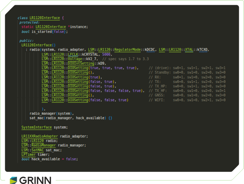
Next, the implementation focused on creating the essential classes needed for the smooth operation of the Lacuna Soft Modem (LSM), as well as classes dedicated to managing sensors and peripherals. Each sensor and peripheral was carefully mapped to its corresponding interface, ensuring optimal communication and efficient data processing within the system.
A central component of this implementation is the LR1120Interface class, which manages communication between the device and both satellite and terrestrial networks.
Setting Up Satellite Connection
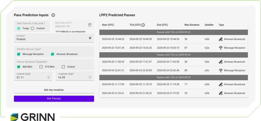
Unlike terrestrial networks, communicating with Lacuna Space satellites requires precise timing and awareness of satellite positions. To successfully transmit data through Lacuna’s satellites, it’s essential to know when a satellite will pass over your location, such as Wrocław. Satellite pass predictions are available on Lacuna’s official website, and satellites also broadcast this information via downlinks to ground devices.
However, the downlink data doesn’t arrive in a single transmission; it is received in chunks. To use this information effectively, these chunks must be collected, reassembled, and stored in the device’s flash memory. Additionally, it’s essential to keep the almanac up to date, as outdated information can lead to missed communication opportunities with the satellite. Managing the almanac can be challenging due to limited testing opportunities, as satellite passes occur only once or twice a day, making real-time debugging and testing difficult.
To address this, we developed an in-office test environment using a LoRa USB dongle that simulates satellite communication. The block diagram below illustrates our setup, which allows us to trigger commands from the PC to the SX1261 transceiver, mimicking the radio transmissions typically sent by the satellite.
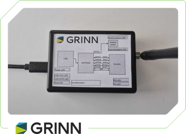
The primary advantage of this approach is the ability to simulate satellite communication as frequently as needed, bypassing the limited windows provided by actual satellite passes.
For USB-to-radio communication, we used the MCP2210 from Microchip to handle the USB interface, and the SX1261 transceiver from Semtech for the radio functionality. On top of this hardware, we developed a software solution in Python to easily manage communication between the PC and the radio module, creating a controllable testing environment for satellite-based LoRaWAN communication.
LoRa Configuration:
Device type: sx1261
Regulator mode: LDO
Frequency: 862700000 Hz
PaPower: 14 dBm
Tx Power: 0 dBm
Spreading factor: SF11
Bandwidth: 500 kHz
Coding rate: 4/5
LDRO: True
Antenna: Internal
Sending 'E0000702001402300700669FFDB40000FF2C138F4D038750'
./build/loraradio/lora-tester -d /dev/hidraw5 -m -w 18 -s
9 -b 125 -q sx1261 -o 4/7 -c -t -f 869.5 --text 080f180328013561328d40
This setup not only accelerates development and testing but also ensures that our almanac management is thoroughly tested and reliable, resulting in smoother satellite communication.
Since the Lacuna almanac is too large to fit into a single transmission, it’s divided into smaller chunks sent individually via satellite. A complete almanac is also available for download from the Lacuna Space website as a structured data set; however, the chunks broadcasted by the satellite are much smaller. Here’s an example of what a raw chunk looks like:
01de53f6b58d4e0cfca1966d06cbe2dfdab061e07406b55b9
eff2a9d1b005bace4e981d6e54db0cc10029d2f3ed62d60ae
Before the almanac chunk can be stored in NVM (Non-Volatile Memory), a wakeup frame needs to be received. A sample wakeup frame might look like this:
E0000702001402300700669FFDB40000FF2C138F4D038750
The wakeup frame consists of the following components:
- Header: 0xE00007020014023007
- Version: 0x00
- Valid from time: 0x669FFDB4
- Localization ID: 0x00
- Service provider mask: 0xFF
- CRC: 0x2C138F4D
- Almanac size: 0x3870
- Block size: 0x50
To ensure proper receipt of each chunk by the device, a prefix with the version number must be added to the chunk itself:
E0010001de53f6b58d4e0cfca1966d06cbe2dfdab061e07406b5
5b9eff2a9d1b005bace4e981d6e54db0cc10029d2f3ed62d60ae.
LOG: D LPP: find_uplink_contact: lookahead 432000s completed in 0ms
LOG: D LPP: find_uplink_contact: lpp2_find_contact: No almanac loaded
LOG: T LR11XX: get_version: hw_version=0x22 use_case=0x02 fw=0x0101
LOG: D LR11XX: rx_lora: sf=11 bw=500000 cr=4/5 freq=864650000 sync=0x34 fixed=0 crc=1
    invert=0 ldro=1 mtu=255 timeout=63000000 timeout_as_symbols=0 duty_cycle=10
    on_time=100352 off_time=1106124 preamble=245 gain=1
LOG: D LR11XX: rx_lora: adapter output: boost=1
LOG: D RadioManager: Standby::rx_lora_read: size=35 snr=-10 rssi=-108 crc_error=0
LOG: D SatMAC: handle_wakeup_frame: time: gps_time=1399977599 unix_time=1715942381 milliseconds=344
LOG: D SatMAC: handle_wakeup_frame: time_until_sequence=2 time_between_wakeup_frames=20 sequence_timeout=18
LOG: D SatMAC: handle_wakeup_frame: waiting 2s for start of sequence
LOG: D LR11XX: rx_lora: sf=11 bw=500000 cr=4/5 freq=864650000 sync=0x34 fixed=0 crc=1 invert=0
    ldro=1 mtu=255 timeout=17996338 timeout_as_symbols=0 duty_cycle=100 on_time=0 off_time=0 preamble=245 gain=0
LOG: D LR11XX: rx_lora: adapter output: boost=1
LOG: D RadioManager: Standby::rx_lora_read: size=119 snr=-9 rssi=-108 crc_error=0
After the almanac is downloaded, a CRC check is performed by calculating the CRC and comparing it to the CRC in the wakeup frame. If the CRC does not match, the entire almanac is deleted, and the device switches to a backup almanac if available and up-to-date. Once the almanac is correctly installed, the device enters deep sleep mode and wakes up every hour to recalculate the satellite's trajectory.
DBG (SatMAC:1015): UplikPass::refresh
DBG (LPP:339): find_uplink_contact: lookahead 432000s completed in 139ms
INF (SatMAC:932): uplink contact found: sat_id=1 start=2024-08-19T15:08:32Z
    tca=2024-08-19T15:09:12Z end=2024-08-19T15:09:51Z duration=79s
INF (SatMAC:1079): uplink contact config: bw=335938 sf=3906 cr=1/3
    nb_header=4 hop=1 detection=None f=862700000
DBG (SatMAC:400): Idle::timer: uplink window will start in 21816s
INF (SatMAC:410): Idle::timer: call again in 3600s
Preparing for Satellite Uplink
After the almanac is successfully downloaded, the system determines the timing for the next available uplink to the satellite. Once the time is set, a timer is initiated to start gathering measurement data in preparation for the uplink. Data collection begins 18 hours before the scheduled uplink, with measurements taken at 6-hour intervals. This approach ensures that data is collected not only immediately before the uplink but also throughout the day, capturing any environmental or operational changes over the period. By the time the uplink occurs, a comprehensive set of measurements is ready for transmission.
In each uplink message, version and flags are mandatory fields. These fields indicate the uplink version and identify the appropriate decoder to use, as well as which sensor data is included in the uplink.
typedef struct {
    uint8_t version;
    uint8_t flags;

    EnvironmentalSensor environmental;
    BatterySensor battery;
    AnalogSensor analog;
    GnssData gnss;
    Satellite satellite;
    RadarSensor radar;
} Message;
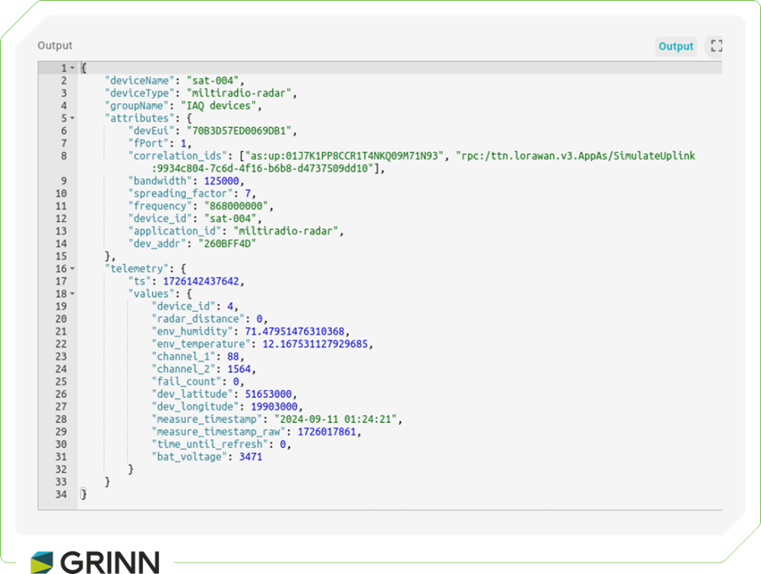
During a transmission window of approximately 30 to 90 seconds—depending on the satellite's position—you can send a message with a payload size between 50 and 230 bytes, depending on the data rate and spreading factor. Once transmitted, the message is processed and may appear on the Lacuna Space Dashboard within 24 hours.
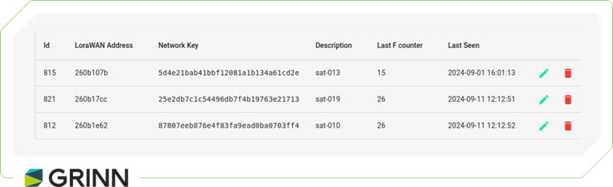
Figure 4. Device preview in Lacuna Space Dashboard.
DBG (LR11XX:792): tx_lrfhss: country=POL bw=335938 grid=3906 cr=1/3
    freq=862700000 power=0 nb_header=4 sequence=0x619A hop=1 size=4
DBG (LR11XX:839): tx_lrfhss: adapter output: dbm=21 pa_sel=1 pa_duty_
    cycle=4 hp_max=7 ramp_time=480us temperature=35°C vdd=3282mV
DBG (LR11XX:209): set_power: vreg=vbat dbm=21 pa_sel=1 pa_duty_
    cycle=4 pa_hp_sel=7 ramp_time=480us
DBG (RadioManager:933): TX::before, timeout: 10000000
    satellite_manager: sat_contact_started
    satellite_manager: uplink successful
In TTN, you can use available decoders such as CayenneLPP or GRPC, where data needs to be encoded to match the selected decoder. Alternatively, if none of the available decoders suit your specific scenario, you have the option to implement a custom decoder.
var decoder_v3 = {
  PROTOCOL_VERSION: 3,
  SENSORS: [
    {
      length: 8,
      values: [
        {
          name: 'env_temperature_1',
          displayName: 'Ambient temperature',
          convert: function (x) {
            return x[0];
          },
          unit: '°C'
        },
        {
          name: 'env_temperature_2',
          displayName: 'Ambient temperature',
          convert: function (x) {
            return x[1];
          },
          unit: '°C'
        },
        {
          name: 'env_temperature_3',
          displayName: 'Ambient temperature',
          convert: function (x) {
            return x[2];
          },
          unit: '°C'
        },
        {
          name: 'env_temperature_4',
          displayName: 'Ambient temperature',
          convert: function (x) {
            return x[3];
          },
          unit: '°C'
        },
        {
          name: 'env_humidity_1',
          displayName: 'Humidity',
          convert: function (x) {
            return x[4];
          },
          unit: '%'
        },
        {
          name: 'env_humidity_2',
          displayName: 'Humidity',
          convert: function (x) {
            return x[5];
          },
          unit: '%'
        },
        {
          name: 'env_humidity_3',
          displayName: 'Humidity',
          convert: function (x) {
            return x[6];
          },
          unit: '%'
        },
        {
          name: 'env_humidity_4',
          displayName: 'Humidity',
          convert: function (x) {
            return x[7];
          },
          unit: '%'
        }
      ]
    },
    {
      length: 1,
      values: [
        {
          name: 'battery_voltage',
          displayName: 'Battery voltage',
          convert: function (x) {
            return x[0];
          },
          unit: 'mV'
        }
      ]
    },
    {
      length: 4,
      values: [
        {
          name: 'analog_1',
          displayName: 'voltage',
          convert: function (x) {
            return x[0];
          },
          unit: 'mV'
        },
        {
          name: 'analog_2',
          displayName: 'voltage',
          convert: function (x) {
            return x[1];
          },
          unit: 'mV'
        },
        {
          name: 'analog_3',
          displayName: 'voltage',
          convert: function (x) {
            return x[2];
          },
          unit: 'mV'
        },
        {
          name: 'analog_4',
          displayName: 'voltage',
          convert: function (x) {
            return x[3];
          },
          unit: 'mV'
        }
      ]
    },
    {
      length: 2,
      values: [
        {
          name: 'latitude',
          displayName: 'latitude',
          convert: function (x) {
            return x[0] * 1000;
          }
        },
        {
          name: 'longitude',
          displayName: 'longitude',
          convert: function (x) {
            return x[1] * 1000;
          }
        }
      ]
    },
    {
      length: 2,
      values: [
        {
          name: 'time_until_refresh',
          displayName: 'time_until_refresh',
          convert: function (x) {
            return x[0] * 1000;
          },
          unit: 's'
        },
        {
          name: 'fail_count',
          displayName: 'fail_count',
          convert: function (x) {
            return x[1];
          }
        }
      ]
    },
    {
      length: 4,
      values: [
        {
          name: 'radar_1',
          displayName: 'Distance',
          convert: function (x) {
            return x[0];
          },
          unit: 'm'
        },
        {
          name: 'radar_2',
          displayName: 'Distance',
          convert: function (x) {
            return x[1];
          },
          unit: 'm'
        },
        {
          name: 'radar_3',
          displayName: 'Distance',
          convert: function (x) {
            return x[2];
          },
          unit: 'm'
        },
        {
          name: 'radar_4',
          displayName: 'Distance',
          convert: function (x) {
            return x[3];
          },
          unit: 'm'
        }
      ]
    }
  ],

  read_int8: function (bytes, pos) {
    if (bytes[pos] === 0xff) {
      return 0xff;
    }

    if (bytes[pos] > 127) {
      bytes[pos] -= 256;
    }

    return bytes[pos];
  },

  read_int: function (bytes, pos) {
    if (bytes[pos + 1] === 0xff && bytes[pos] === 0xff) {
      return 0xffff;
    }

    return (bytes[pos + 1] << 8) + bytes[pos];
  },

  read_int32: function (bytes, pos) {
    return (bytes[pos + 3] << 24) + (bytes[pos + 2] << 16) + (bytes[pos + 1] << 8) + bytes[pos];
  },

  decode: function (msg) {
    var bytes = msg;
    var i, j;

    if (typeof msg === 'string') {
      bytes = [];
      for (i = 0; i < msg.length; i += 2) {
        bytes.push(parseInt(msg.substring(i, i + 2), 16));
      }
    }

    var version = bytes[0];
    if (version != this.PROTOCOL_VERSION) {
      return {error: 'protocol version ' + version + " doesn't match v3"};
    }

    var flags = bytes[1];
    var result = {
      'protocol_version': version,
      flags: flags
    };
    var pos = 2;

    for (i = 0; i < this.SENSORS.length; i++, flags >>= 1) {
      if ((flags & 1) !== 1)
        continue;

      var sensor = this.SENSORS[i];
      var x = [];

      // convert data to 16-bit integer array
      for (j = 0; j < sensor.length; j++) {
        if (i === 0) {
          x.push(this.read_int8(bytes, pos));
          pos += 1;
        } else {
          x.push(this.read_int(bytes, pos));
          pos += 2;
        }
      }

      // decode sensor values
      for (j = 0; j < sensor.values.length; j++) {
        var value = sensor.values[j];

        if ('convert' in value) {
          result[value.name] = {
            displayName: value.displayName,
            value: value.convert.bind(this)(x)
          };

          if ('unit' in value) {
            result[value.name]['unit'] = value.unit;
          }
        }
      }
    }

    return result;
  }
};
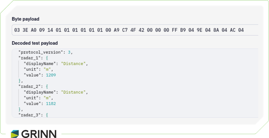
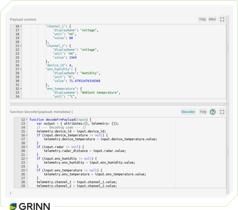
A decoded message might look like this:
Integrating TTN and ThingsBoard for IoT Data Visualization
Data from IoT devices can be visualized using various platforms, and ThingsBoard (TB) is a robust option for integrating and managing these data streams. ThingsBoard can connect to multiple backend systems, including AWS IoT, Azure IoT Hub, Google Cloud IoT, and even directly to The Things Network (TTN).
To start, click on Integrations in the Integrations Center.
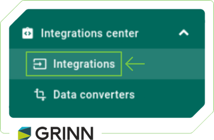
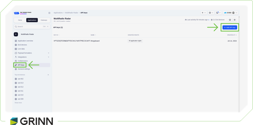
Next, select The Things Stack Industries and assign it a meaningful name. In the following step, generate an API key in TTN and paste it into your ThingsBoard integration.
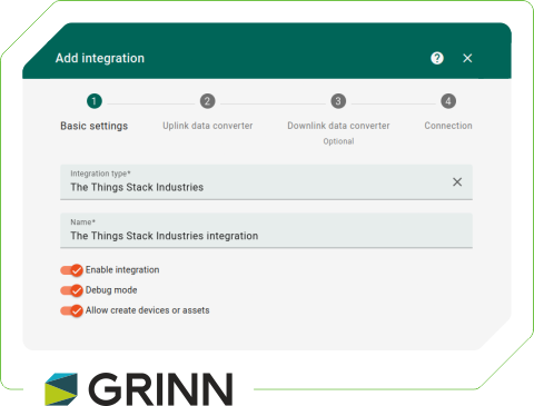
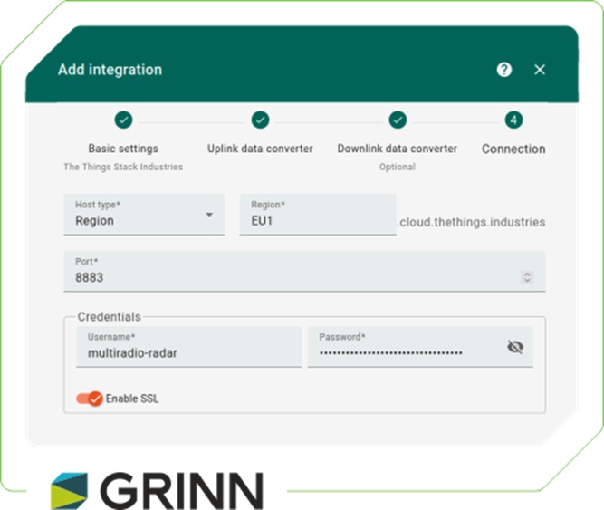
After adding the integration, adjust the payload decoder to match your data format.
This setup enables data transmitted via LoRaWAN and received by Lacuna to flow into ThingsBoard for visualization and further processing. In our project, we’re collecting temperature and humidity data from the SHTC3 sensor, which is transmitted through the Lacuna network and received in TTN. After the data is decoded in TTN, it is forwarded to ThingsBoard, where we can visualize it. GPS data is also processed in the same way.
If a custom decoder is needed for the data format in ThingsBoard, it can be easily added through TB’s interface, allowing for quick validation of test results.
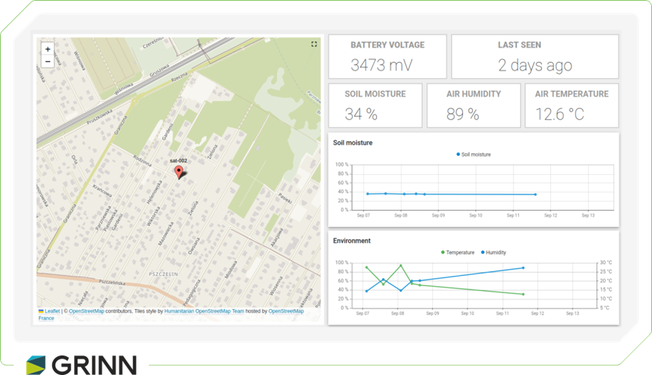
Once temperature, humidity, and GPS data are available in ThingsBoard, they can be visualized with customizable charts and a map widget for GPS tracking. Below is a screenshot of our setup, showing real-time displays of these measurements. ThingsBoard can also generate detailed graphs to show temperature and humidity trends over time and plot GPS coordinates on a map, enabling device movement or position tracking. This provides a comprehensive view of the collected data for in-depth analysis and decision-making.
Summary
By the end of this walkthrough, we have covered the full path of satellite-based LoRaWAN communication with Lacuna Space: from device registration and protocol choices, through almanac handling and uplink timing, all the way to decoding and visualizing data in TTN and ThingsBoard.
Together with part one, this should give you a complete picture of how to design, test, and operate a low-power IoT system that doesn’t rely on terrestrial connectivity. You can build on this foundation to optimize power consumption, improve reliability, or scale the solution for real-world deployments.

 Daniel Smyk